Sunday, June 11, 2017

Journey wooden clock

I mentioned my interest in unique clock design when I posted about my first wooden clock. After completing that clock, I purchased plans for Clayton Boyer's Journey, a more complicated and intricate clock. It's a lot of fun to watch!

This is going to be another long post. :)


The first phase of the project is all electronic, converting files and adapting the design to be produced on my CNC machine. Considerations include material size, bit selection, and reducing material use. Here you can see the laptop's view of the CNC controls and the webcam monitor.


Besides sanding, many pieces need additional touches. These supports are drilled to allow allen set screws, which secure them to the clock's arbors.


Arbors are cut to length and polished using the paper plans as a guide.


The clock's unique serpentine race is too long for my CNC to cut in one pass, so I cut half of it, fed it through, then cut the other half. The waste piece from the race looks a lot like an serpent, especially if you draw eyes on it. After taking the pictures, I glued the two cut pieces together to form the race.


Most of the clock is made from birch plywood, which keeps its size well and doesn't warp much in humidity or with the change of temperature. That's very important for gear precision, but for the face and hands I went with something fancier, using cherry and walnut to provide color and contrast.

I wanted to inlay roman numerals in the face, so I started by engraving them in the wood with a V bit.


I cut both the face and the hypocycloid gear from the same piece of cherry, finished the cherry with an oil-poly mixture, then filled the engraving with superglue mixed with brass powder that I'd made by grinding a brass rod using a Dremel tool.
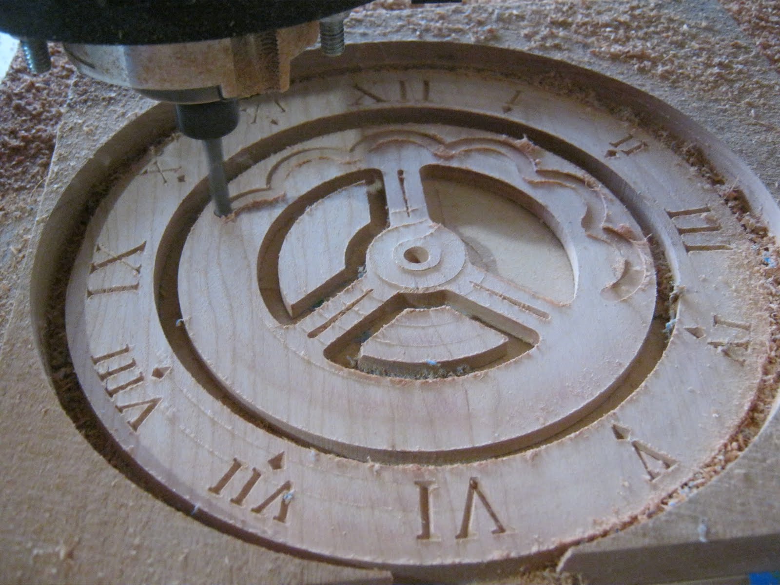


After curing, the superglue-brass was sanded off and the oil-poly mixture reapplied.


The hands were cut from a single piece of walnut, finished with the same mix, then the full face was glued together.


You may have noticed the pegs sticking out of the hour hand. The hour hand isn't driven directly by any normal gear. Instead, a cam on the back of the minute hand forces the hour hand around the hypocycloid gear in a way that easier to show than to describe.

The minute hand's movement is also intriguing. It's attached to a gear with a few more teeth than the stationary sun gear. A planet gear (the pinion moving around the outside of these two gears) forces the teeth into alignment as it travels, which causes the minute gear (and minute hand) to rotate. Again, this is easier to understand by watching than reading. For this video, I've removed the escapement and allowed the clock to run freely at a much faster rate.

Finally, the clock is complete. A chrome ball runs down the serpentine race, making electrical contact to engage the motor. The motor lifts the serpentine race, which provides the weight for the clock to run for several seconds until the process repeats. It's a lot of fun to watch!


Thanks for reading!

Sunday, June 4, 2017

CNC Diamond Drag Bit

One of the cool things you can do with a CNC machine is engrave metals and hard plastics using a drag bit, which is a pointed bit with a cheap, industrial-grade diamond. Unlike normal CNC bits, a drag bit doesn't spin while it works. Instead, it presses against the material as the machine drags it along the surface. The results look really cool and it's useful for engraving items like Zippo lighters

Unfortunately, drag big holders are too expensive (over $150) for most hobbyists that aren't using them to bring in business. Interestingly, the bits themselves are cheap (~$10). So I set about to make a budget-friendly holder.

My first attempt used a 1/4" aluminum tube capped with a small washer to prevent the bit from falling out. A piece of plastic goes between the spring and bit. The tube was capped with a screw to allow the bit to be replaced.


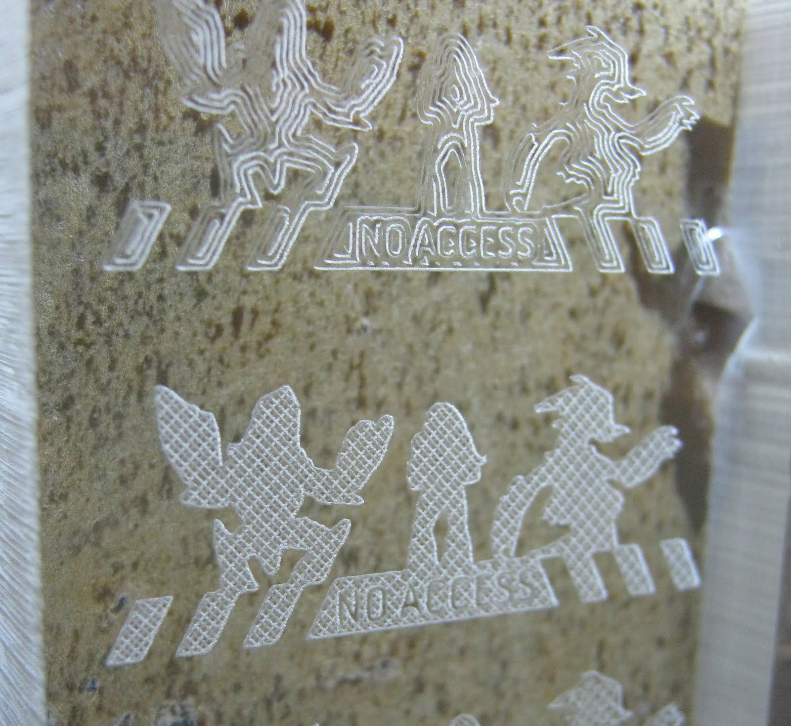
I put the entire tube in the router as though it were a 1/4" CNC bit and turned the router off to prevent spinning. A couple samples in scrap acrylic yielded a mixed success. The general shapes are visible, but the tube was too long with too much flex.


I reused the design from my dust boot to mount a larger support to the machine. The length of wood prevents flexing.


A thumb screw holds the tube in place. In this picture, you can see how the washer allows only the tip of the drag bit out. It lacks the vertical give of a professional holder, so it only works on flat  work surfaces.


The new tests are much sharper! This is the level of quality I was striving for. You can see how the cross hatch pattern looks less scribbly.


My first project with the new drag bit was to make a replacement piece for a board game I enjoy. The original game piece was large, flimsy, and blocked that players' view of the spaces behind. For scale, the green bug on top is about the size of a quarter.

Sunday, April 2, 2017

CNC Dust Boot

Using the CNC machine can be a messy job. Cutting hardwood often leaves a wonderful scent in the air, but shavings get everywhere. The worst offender, by far, was some black HDPE plastic I cut. The shavings consumed much more volume than the original piece, they static-clung to everything and got everywhere.


The common solution for CNC owners, especially those with a good dust collection system in their workshops, is to create a dust boot (or dust shoe). Rockler sells a dust boot for my machine, but it costs more than I wanted to pay. I decided to take the hobbyist route and make my own instead.

All the dust boots I've seen require modifying the machine in some form. Usually they require replacing existing bolts with longer ones or replacing the clamp or spacer in some form. I wanted a solution that worked without modifications. The existing bolts are long enough to put an extra nut on, but there's no space for material in addition to the nuts. After taking some measurements, I determined I could use the existing bolt tails if I could find a nut that would protrude through the material to access the bolt threads. T-nuts did the job perfectly. The picture does a better job of explaining this than I do.


I ended up making two prototypes out of plywood before finalyzing it with acrylic, which is much more expensive.


To complete the dust boot, I added the skirt, which I think was intended for conveyor belt systems. Copper tape and a grounding wire were also added so I can ground the vacuum hose and prevent the static cling that occurs on the hose's exterior.

Wednesday, March 8, 2017

Piano Shelves

If you follow the blog, you've seen a lot of shelves. This is the first time I've attempted indoor shelves, where function isn't the sole consideration. These plans are of my own design. I visited the lumberyard for a separate project and found a limited acquisition of myrtlewood they had on their clearance rack. The lumber was rough in several spots, but had a lot of great character. We purchased these three boards.


Everything was cut down to size with a circular saw and evened out on the table saw.


I cut out supports on the CNC machine and glued them together three-ply. This could have been done with a table saw and miter saw, but I thought the recess would be a fun, easy touch.


After routing grooves into the side panels, I glued the supports in place, stained everything. I did a test fit on the wall prior to final cuts and finishing.


A couple coats of semi-gloss polyurethane, everything really shines. It's ready to be hung on the wall.


The supporting pieces are attached to the wall. The main supports are held in place with Spax lagbolts, which are thin, 6" lag screws that can hold around 900 pounds apiece. The supports will carry the weight of the finished shelves, which are simply be lifted over the supports and held in place with gravity.


The finished shelves hang on the wall where they don't cover the heat register. And they look great.

Friday, December 30, 2016

Mahogany Cribbage Board

A good friend of mine approached me about making a cribbage board for his parents. He provided a couple pieces of mahogany, some spray-on shellac, and design ideas. I helped out with the tools.

Once we worked out a design and performed a few test cuts, the CNC machine did most of the work.


Prior to cutting the final cut, I took a 90-degree V bit and cut around the profile of the piece. This results in the 45-degree champfer you see around the edge, rather than a 90-degree sharp corner. It makes the project look more polished and professional.


My friend added two or three coats of shellac and the board came out perfectly. It'll make a great gift.

Sunday, December 25, 2016

Paradise Jewelry Box

A year or two back, my father suggested I should make a jewelry box for my mother. It took me a while to find a design I liked and work up the courage to put it all together. The box is made from solid maple, cut on the CNC machine, and finished with oil and polyurethane.

The box top (the lid) was too wide for anything I could find at the lumber yard, so I glued together a couple pieces.


The sides and top of the box have a beautiful V-carved pattern. This is a cornerstone feature of the software that came with my CNC machine. It's easy to design using only an image and a lot of fun to watch. I took a video of the top being carved and sped it up. It's mesmerizing.

When the cutting is complete, you can't tell the lid was once separate pieces of wood.


The font and back are similarly patterned, then glued together.


I finished the box with a mixture of boiled linseed oil and polyurethane, thinned down with mineral spirits. On the bottom, I engraved the date and a hand-written message, which I'd scanned into the computer and converted to a CNC path.


After adding a short piano hinge and rubber feet, the box is complete! It turned out well. Merry Christmas, Mom!


Sunday, October 30, 2016

Simplicity Wooden Clock

[Updated August 2017 with walnut hands]

I've always had a thing for unique clocks and timepieces. They're harder to find than you might think. Try Googling it. Go ahead, I'll wait. All done? Great. Then you've noticed that any "unique clocks" or similar search mostly returns your traditional clock hands with a different printed face. These are often humorous and entertaining, but not really what I want. One day I ran across plans for a wooden clock and knew I was hooked.

This is going to be a long post. :)


In August of 2009, I purchase plans for Simplicity. I had no woodworking skills at the time and had planned to make all the parts by hand on a scroll saw. I had a friend who provided the tools and helped me in purchasing the birch plywood. However, the time commitment didn't meet his interest level, so he bailed on the project. Lacking the proper tools, I put the project aside for several years. I'm grateful he selected the plywood for me. It's what I ended up using in the final project.

Five years later, I had started doing the projects on this blog and purchased a CNC machine. It's the most awesome tool ever! After a couple dozen hours tweaking the design files, I started cutting pieces.


I learned a lot about my new CNC during this process. If I had it to do again, I'd be faster, make fewer mistakes, and throw away far fewer bad pieces. Regardless, the final pieces came together well.


The dremel tool was invaluable for cutting the brass pieces, which are both functional and visually striking in the wooden clock.


Just when everything was finally coming together, we packed everything up and moved. The new house's projects took up most of my free time and you can see many of them chronicled here. A couple months ago, I got around to working on the clock again. By this point, I was worried that my novice approach and compounded mistakes would prevent the clock from ever running. Still, it looked nice!


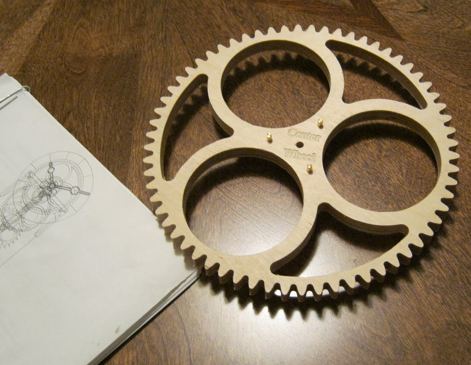
One of my biggest problems was trying to use a hand drill in place of a drill press. The precision of the clock requires true, perpendicular drilling. I ended up needing to fill in, sand, and re-drill some of the holes on the drill press I have since acquired. In this picture, I have the escapement gear filled in and ready to be sanded and drilled.


At last everything was filed down and sanded to perfection. The gears meshed well and the frame was mounted on the wall for final troubleshooting. I needed a weight for initial testing and grabbed the first thing I saw in the kitchen: a stock pot. It looked funny, but worked great. First, I ran the clock without any escapement to break in the gears. Afterwards, the escapement and pendulum were added.


Before tinkering and adjustments, the clock would run for a few minutes at a time before seizing. The first time it ran through the night was as exciting as when my son first slept through the night. I placed a scale under the pot to determine how much weight the scale would need to bear before the clock would stop. Subtracting the scale's reading from the pot's weight gave me an idea of how much weight the clock requires to run. I made some weights, filled them with pennies, and returned the pot to my wife.


With the weights, the full clock is complete! It actually runs, tells good time, and is tremendously satisfying to watch. I'm stoked! The clock is magnificent and has a pleasant, steady tick. It runs for maybe 30 hours on a wind using a 2.75 lb weight.


Thanks for reading. It's been a long road and I'm very pleased with how everything turned out.

(August  2017 update) The clock has been ticking steadily for months now! I finally decided it was too hard to read the time from a distance, so I replaced the original birch ply hands with walnut hands. They provide a nice contrast.